Motorola MC68000 – 16/32-bit CISC microprocessor with a 16-bit data bus and 24-bit addressing
Definition
The MC68000 is a “16/32-bit” CISC microprocessor: it implements an instruction set and registers in 32-bit, but it uses a 16-bit external data bus. It was introduced in 1979 by Motorola and became a widely used base for embedded systems and computers of the era thanks to a linear memory model (no segmentation) and a relatively “clean” programming model compared to many contemporaries.
Practically, the 68000 offers an effective compromise: a rich internal architecture (wide registers, flexible addressing modes, structured exception handling) with an external interface compatible with 16-bit logic and memories.

16/32-bit architecture: what it means
The “16/32-bit” concept comes from three main elements:
32-bit general-purpose registers and instructions that support long (32-bit) operations.
16-bit internal ALU datapath (with 32-bit operations executed in multiple phases).
16-bit external data bus, so 32-bit transfers require two bus cycles (when data is not already buffered internally, and depending on bus conditions).
The result is very effective behavior on structured code and in systems where 16-bit memory was a good cost/performance balance.
Address space: 24-bit and 16 MB linear
The MC68000 provides a 24-bit external address bus, so it can address up to 16 MB of physical space, with byte addressing. Internally, addresses are handled with 32-bit registers, but the upper 8 bits are not physically present on the external bus.
In practice:
no segments to manage;
a simpler linear memory map for firmware, operating systems, and drivers;
ample room for memory-mapped I/O.
Registers: 8 data registers and 8 address registers
The register set is one of the 68000’s strengths:
D0–D7: 8 × 32-bit data registers, used for arithmetic/logic and as general operands.
A0–A7: 8 × 32-bit address registers; A7 is the stack pointer (with a distinction between user and supervisor stacks).
PC (program counter) and SR (status register) complete the model.
This reduces memory traffic for temporaries and makes assembly more orthogonal and regular.
User/supervisor modes and exception handling
The MC68000 provides two privilege levels:
Exceptions and interrupts switch the processor into supervisor mode with a dedicated stack, a key detail for robustness and system reliability.
Bus and key signals: AS, UDS/LDS, R/W, and DTACK
The 68000 bus interface is designed to support 8- or 16-bit transfers and to tolerate slow peripherals through handshaking:
AS (address strobe): indicates that address and cycle type are valid.
UDS/LDS (upper/lower data strobe): select the upper or lower byte during transfers on the 16-bit bus.
R/W: indicates read or write.
DTACK: peripheral/memory handshake to terminate the cycle; it enables “dynamic” wait insertion without fixed wait-state timing.
Practically, UDS/LDS are also crucial for byte transfers at even/odd addresses and for interfacing 8-bit devices.
Instruction prefetch: two-word (4-byte) queue
To improve performance, the MC68000 uses a simple prefetch mechanism with a two-word queue (total 4 bytes). This reduces some bus idle time between instruction fetch and execution, especially when memory responds quickly or code is sequential.
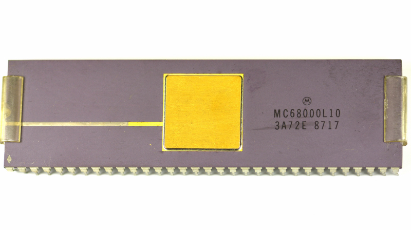
Package and typical integration
The MC68000 is well known for availability in a DIP 64 package, common on through-hole boards and serviceable systems. From an integration standpoint it typically requires:
decoding logic to generate chip selects for RAM/ROM/peripherals;
optional wait/handshake logic (or DTACK driven by peripherals);
attention to bus layout (width, strobes, timing).
Sketch of the most important connections
                 address bus (A1..A23) + cycle control (AS, R/W, UDS/LDS)
        ┌──────────────────────────────────────────────────────────────┐
        │                    decode logic / glue logic                  │
        │  RAM/ROM/peripheral chip selects + DTACK handling             │
        └───────────────────────────────────┬──────────────────────────┘
                                            │
                                            ▼
                           ┌────────────────────────────────┐
                           │            MC68000             │
                           │  16/32-bit CPU, 16-bit data bus │
                           │  A1..A23, D0..D15               │
                           │  AS, UDS/LDS, R/W, DTACK        │
                           └───────────────┬────────────────┘
                                           │
                                           ├────────► RAM / ROM (16-bit or 2×8-bit)
                                           └────────► memory-mapped peripherals / I/O
Table 1 – Identification data and specifications
| Characteristic | Indicative value |
|---|
| Device | Motorola MC68000 |
| Class | 16/32-bit CISC microprocessor 100 MHz |
| Introduction | 1979 |
| External data bus | 16-bit (D0–D15) |
| External address bus | 24-bit (up to 16 MB) |
| Addressable space | 16 MB linear (byte addressing) |
| Main registers | 8× data (D0–D7), 8× address (A0–A7), PC, SR |
| Privilege levels | User / supervisor |
| Instruction prefetch | 2-word queue (4 bytes) |
| Typical bus signals | AS, UDS/LDS, R/W, DTACK |
| Common package | DIP 64 |
Table 2 – Operational and design considerations
| Aspect | Practical meaning |
|---|
| 24-bit linear addressing | Simple memory map, no segmentation, easy memory-mapped I/O |
| UDS/LDS | Upper/lower byte selection on 16-bit bus, natural support for 8-bit devices |
| DTACK (handshake) | Supports slow memories/peripherals without rigid timing; wait “on demand” |
| Rich register set | Reduces memory traffic, regular assembly style, good performance on structured code |
| User/supervisor | Solid base for OS/monitors with privilege separation |
| 2-word prefetch | Improves throughput on sequential streams; sensitive to memory latency |
| Board-level integration | Requires glue logic for decoding and bus-signal handling, especially in complex systems |