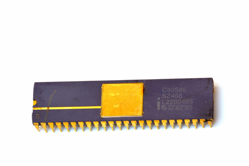
The Intel C82586 was an Ethernet LAN Coprocessor released in 1982 and was part of the 80186 and 80188 systems.
Ethernet LAN coprocessor
Definition
An Ethernet LAN coprocessor is an integrated circuit that implements a substantial part of the link-layer control needed for Ethernet networking, reducing the workload on the host CPU. A device in the Intel 82586 class behaves as an I/O coprocessor: the host CPU prepares commands and data structures in shared memory, then the coprocessor autonomously manages much of frame transmit/receive handling, coordinating DMA transfers to/from RAM and interfacing to the Ethernet physical side through a transceiver/MAU (and magnetics).

Why it is used
Without a LAN coprocessor, the CPU would typically need to:
Move packet data between RAM and the network interface with frequent CPU involvement
Manage transmit/receive queues and buffer lifecycles at a very low level
React to medium-related events and timing constraints with higher overhead
An 82586-like coprocessor shifts much of this complexity into dedicated hardware/microcode, providing:
DMA to move packet payloads without continuous CPU copying
A structured descriptor model (command/tx/rx) in shared memory
Parallel operation in which the CPU orchestrates and the coprocessor executes, within memory/bus bandwidth limits
Functional architecture
A practical way to view an 82586-class controller is as two cooperating engines:
Receive unit (RU): accepts frames from the physical interface, validates them, and places them into host RAM using receive descriptors and buffers
Command/transmit unit (CU): fetches commands and transmit buffers from RAM, transmits frames onto the medium, and updates status/statistics back into RAM
The central idea is shared-memory messaging: software posts work by building control blocks and lists in RAM; hardware consumes those structures and writes results back into the same memory.
CPU–coprocessor communication model (shared memory)
The host CPU typically:
Initializes global pointers and configuration/control structures
Allocates and links descriptors and buffers (TX and RX)
“Kicks” the coprocessor when new work is ready (via channel attention or an equivalent mechanism, depending on board design)
Handles interrupts or polls status, then recycles completed buffers/descriptors
The coprocessor:
Reads the next commands from a command list in RAM
Executes transmit/receive using descriptor chains (buffers/frames)
Writes completion flags, status, and counters back into RAM
Optionally asserts interrupts for completion, receive events, or error conditions
Sketch of the most important connections
                 ┌──────────────────────────┐
                 │         Host CPU          │
                 │ Driver + RAM allocation   │
                 └───────────┬──────────────┘
                             │  Host bus (I/O or memory-mapped)
                             │  + signals: RD/WR, IRQ, CA, RESET
                             ▼
                     ┌───────────────┐
                     │  Intel 82586  │
                     │ LAN coprocess.│
                     │  DMA + CU/RU  │
                     └──────┬────────┘
                            │  DMA access to RAM (buffers + descriptors)
                            ▼
                 ┌──────────────────────────┐
                 │ Shared RAM               │
                 │ - SCP/ISCP/SCB           │
                 │ - Command blocks (CB)    │
                 │ - Tx buffer descriptors  │
                 │ - Rx frame/buffer desc.  │
                 │ - Packet buffers         │
                 └──────────────────────────┘
                            ▲
                            │ network data (tx/rx) via MAC/PHY path
                            ▼
              ┌──────────────────────────────┐
              │ Transceiver / MAU + magnetics │
              │ (Ethernet physical interface) │
              └──────────────┬───────────────┘
                             ▼
                          Ethernet LAN
Important operational details (drivers and performance)
1) Lists and descriptors as the CPU–chip contract
The driver builds linked descriptors for:
The coprocessor “consumes” ready descriptors, writes completion flags/status, then advances to the next entry. This enables pipelining and can reduce interrupt overhead when the driver batches work.
2) Concurrency and synchronization
The CPU can run while the coprocessor is active, but synchronization is required at ownership boundaries:
A buffer must not be reused until the coprocessor marks it complete
When updating list pointers, ordering and ownership rules must be respected (platform-dependent memory ordering considerations)
The driver must handle backpressure states such as “busy,” “no resources,” or equivalent status conditions
3) Memory bandwidth as the main bottleneck
Real throughput is often dominated by:
Shared RAM latency and bandwidth
Bus contention between CPU and coprocessor DMA
Descriptor and buffer layout (locality, fragmentation, and the cost of walking many small buffers)
4) Root-pointer initialization
Controllers in this family typically use an initialization “root” mechanism (commonly described with SCP/ISCP/SCB-style structures). After reset and a channel-attention event, the coprocessor reads these root pointers from RAM to locate the primary control/status blocks, and then starts walking the command and receive structures.
Table 1 – Identification data and specifications
Parameter | Value and notes |
|---|
Role | Ethernet LAN coprocessor using a shared-memory model |
Standard context | IEEE 802.3 Ethernet (historical 10 Mb/s context) |
Transfers | DMA to move frames and buffers between RAM and the network interface |
Parallelism | CPU orchestrates; coprocessor runs autonomously and writes status back to RAM |
Buffer management | RAM-based descriptors and lists (commands, TX, RX) |
Table 2 – Shared-memory structures and flow
Structure | Operational purpose |
|---|
SCP/ISCP (root pointers) | Initialization/config pointers to the main control structures |
SCB (system control block) | Global CPU–chip control and status (run/stop, unit state, event flags) |
CBL (command block list) | List of commands the coprocessor walks and executes |
RFA (receive frame area) | Receive region: frame/buffer descriptors plus backing buffers |
Channel attention + interrupt | Mechanisms to notify new work and signal completions/events |