
by Al222 (24908 pt) · 2026-Feb-02
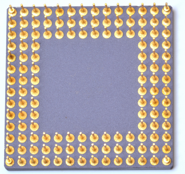
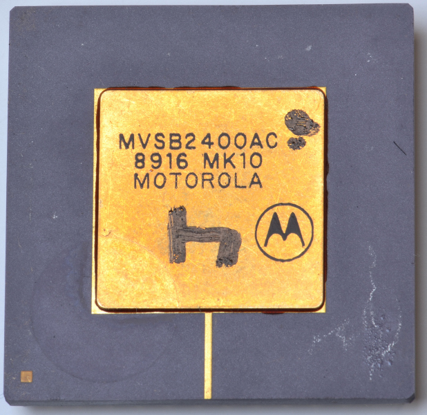
Motorola MVSB2400DefinitionThe Motorola MVSB2400 is a “VSBchip”: a VLSI device (implemented as a gate array in a 132-pin PGA package) designed to implement most of the functions required for a VSBbus (VME Subsystem Bus) interface in VMEbu...