|
|
|
| App | Log in |
|
|
|
| App | Log in |
 | "Descrizione" by Al222 (24917 pt) | 2026-Feb-02 18:51 |
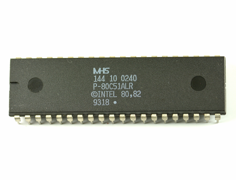
MHS P-80C51
Definition
The MHS P-80C51 is an 8-BIT MICROCONTROLLER compatible with MCS-51 ( 8051-class core) built in CMOS technology, designed for embedded systems where parallel I/O, hardware timing, and serial communications are required with controlled power consumption.
The “P-80C51” variant integrates on-chip program ROM and internal data RAM; in addition, even as a single-chip device, it can address external memory (program and data) up to 64K for each space, enabling scalable designs (from “all on-chip” to systems with external memory and peripherals).
Integrated memories: 4K × 8 ROM and 128 × 8 RAM
ROM 4K × 8: stores the firmware (program) inside the chip. It is suitable for compact control applications, state machines, I/O handling, and simple protocols.
RAM 128 × 8: is the internal data memory used for variables, stack, small buffers, and “hot” data with minimal latency.
When the application requires larger firmware or data, external memory is used: the internal ROM remains useful for base versions or for “core” firmware in hybrid systems.
Three 16-bit counter/timers (time-base and measurement)
The device includes THREE 16-BIT COUNTER/TIMERS, useful for:
System time-base (periodic ticks).
Duration measurements and deterministic delays.
Event counting (external pulses) and protocol timing.
Practically, having three timers reduces the need for software time-sharing and makes it easier to handle serial, I/O, and timed sequences concurrently.
4 × 8-bit ports: 32 I/O lines
The 4 ports of 8 bits provide a total of 32 programmable I/O lines. In real use they support:
Direct interfacing to digital sensors, keys, LEDs, relays (via drivers), latches, and expansion buses.
Alternate functions and/or use as a multiplexed external bus (typical of the MCS-51 family when external memories are used).
Serial: multiprocessor communications, I/O expansion, full-duplex UART
An integrated serial port is provided and can be used as:
A channel for multiprocessor communications (address recognition/filtering on a shared bus).
A link for I/O expansion (reduced parallel wiring using serial devices).
A full-duplex UART for diagnostics, service console, or connection to peripherals (via external transceivers if required).
Boolean processor (bit-level processing)
The term BOOLEAN PROCESSOR indicates the availability of instructions and hardware mechanisms oriented to single-bit manipulation:
Logical operations and tests on bits in dedicated bit-addressable areas.
Efficient management of flags, masks, status signals, and bit-wise I/O.
In practice, many control logics (interlocks, state conditions) become more compact and faster than a purely byte-oriented approach.
Full static operation (HZ → MHZ)
FULL STATIC OPERATION means the internal logic can operate with the clock reduced down to very low frequencies (even near 0) without losing the state of registers and internal RAM. This enables power-saving strategies based on clock reduction and works well with IDLE/POWER DOWN modes typical of this microcontroller class.
Low voltage: 2.7 V – 5.5 V at 16 MHZ
The device is specified to operate from 2.7 V to 5.5 V at 16 MHZ (low-voltage version). The practical benefit is compatibility with battery-powered systems or non-ideal 5 V supplies, while maintaining useful performance without complex power regulation.
Memory addressing capability: 64K ROM and 64K RAM (external memories)
The P-80C51 supports addressing:
64K of external ROM space (program/code space).
64K of external RAM space (external data space, often called XDATA).
This enables:
Firmware larger than the internal ROM (external EPROM/FLASH).
Extended buffers and data areas (external RAM) and memory-mapped peripherals.
Sketch of the most important connections
                 ┌──────────────────────────────┐
                 │         EPROM / FLASH         │
                 │  (external program up to 64K) │
                 └──────────────┬───────────────┘
                                │ code bus (addr/data + control)
                                ▼
                       ┌──────────────────┐
                       │    MHS P-80C51   │
                       │ 8-BIT CMOS MCU   │
                       │ ROM 4K×8         │
                       │ RAM 128×8        │
                       │ 4×8 I/O PORTS    │
                       │ 3× 16-BIT TIMERS │
                       │ UART + OSC/CLK   │
                       └───────┬──────────┘
                               │
                               ├────────► I/O → sensors / drivers / latches / LEDs / relays
                               │
                               ├────────► UART → multiprocessor / expansion / debug
                               │
                               └────────► (opt.) external RAM → up to 64K (data space)
Table 1 – Identification data and specifications (English)
| Characteristic | Typical value |
|---|---|
| Device | MHS P-80C51 |
| Class | 8-BIT MICROCONTROLLER ( MCS-51 family, 8051-class core) |
| Technology | CMOS |
| On-chip ROM | 4K × 8 |
| On-chip RAM | 128 × 8 |
| I/O ports | 4 × 8-BIT (32 lines) |
| Timers/counters | THREE 16-BIT COUNTER/TIMERS |
| Serial | Serial port: multiprocessor / I/O expansion / full-duplex UART |
| Logic features | BOOLEAN PROCESSOR (bit-addressable) |
| Supply | 2.7 V – 5.5 V at 16 MHZ |
| External memory addressing | 64K ROM + 64K RAM |
Table 2 – Operational and design aspects (English)
| Aspect | Practical meaning |
|---|---|
| FULL STATIC OPERATION | Clock can be reduced for power saving without losing internal state |
| ROM 4K×8 | Compact on-chip firmware; reduces external components in simple applications |
| RAM 128×8 | Stack and critical variables; external RAM is typically added for large buffers |
| 3 × 16-bit timers | Concurrent tick generation, measurements, and protocol timing |
| 32 I/O lines | High I/O density; can serve as external bus in designs with external memory |
| Multiprocessor/UART serial | Robust shared-bus communication or full-duplex link for debug/peripherals |
| 2.7–5.5 V @ 16 MHZ | Suitable for low-voltage systems while maintaining good performance |
| External 64K ROM + 64K RAM | Scalability: larger firmware/data and memory-mapped peripherals |
| Evaluate |